Architecture and Concepts
Longhorn creates a dedicated storage controller for each volume and synchronously replicates the volume across multiple replicas stored on multiple nodes.
The storage controller and replicas are themselves orchestrated using Kubernetes.
For an overview of Longhorn features, refer to this section.
For the installation requirements, go to this section.
This section assumes familiarity with Kubernetes persistent storage concepts. For more information on these concepts, refer to the appendix. For help with the terminology used in this page, refer to this section.
- 1. Design
- 2. Longhorn Volumes and Primary Storage
- 3. Backups and Secondary Storage
- Appendix: How Persistent Storage Works in Kubernetes
1. Design
The Longhorn design has two layers: the data plane and the control plane. The Longhorn Engine is a storage controller that corresponds to the data plane, and the Longhorn Manager corresponds to the control plane.
1.1. The Longhorn Manager and the Longhorn Engine
The Longhorn Manager Pod runs on each node in the Longhorn cluster as a Kubernetes DaemonSet. It is responsible for creating and managing volumes in the Kubernetes cluster, and handles the API calls from the UI or the volume plugins for Kubernetes. It follows the Kubernetes controller pattern, which is sometimes called the operator pattern.
The Longhorn Manager communicates with the Kubernetes API server to create a new Longhorn volume CR. Then the Longhorn Manager watches the API server’s response, and when it sees that the Kubernetes API server created a new Longhorn volume CR, the Longhorn Manager creates a new volume.
When the Longhorn Manager is asked to create a volume, it creates a Longhorn Engine instance on the node the volume is attached to, and it creates a replica on each node where a replica will be placed. Replicas should be placed on separate hosts to ensure maximum availability.
The multiple data paths of the replicas ensure high availability of the Longhorn volume. Even if a problem happens with a certain replica or with the Engine, the problem won’t affect all the replicas or the Pod’s access to the volume. The Pod will still function normally.
The Longhorn Engine always runs in the same node as the Pod that uses the Longhorn volume. It synchronously replicates the volume across the multiple replicas stored on multiple nodes.
The Engine and replicas are orchestrated using Kubernetes.
In the figure below,
- There are three instances with Longhorn volumes.
- Each volume has a dedicated controller, which is called the Longhorn Engine and runs as a Linux process.
- Each Longhorn volume has two replicas, and each replica is a Linux process.
- The arrows in the figure indicate the read/write data flow between the volume, controller instance, replica instances, and disks.
- By creating a separate Longhorn Engine for each volume, if one controller fails, the function of other volumes is not impacted.
Figure 1. Read/write Data Flow between the Volume, Longhorn Engine, Replica Instances, and Disks

1.2. Advantages of a Microservices Based Design
In Longhorn, each Engine only needs to serve one volume, simplifying the design of the storage controllers. Because the failure domain of the controller software is isolated to individual volumes, a controller crash will only impact one volume.
The Longhorn Engine is simple and lightweight enough so that we can create as many as 100,000 separate engines. Kubernetes schedules these separate engines, drawing resources from a shared set of disks and working with Longhorn to form a resilient distributed block storage system.
Because each volume has its own controller, the controller and replica instances for each volume can also be upgraded without causing a noticeable disruption in IO operations.
Longhorn can create a long-running job to orchestrate the upgrade of all live volumes without disrupting the on-going operation of the system. To ensure that an upgrade does not cause unforeseen issues, Longhorn can choose to upgrade a small subset of the volumes and roll back to the old version if something goes wrong during the upgrade.
1.3. CSI Driver
The Longhorn CSI driver takes the block device, formats it, and mounts it on the node. Then the kubelet bind-mounts the device inside a Kubernetes Pod. This allows the Pod to access the Longhorn volume.
The required Kubernetes CSI Driver images will be deployed automatically by the longhorn driver deployer. To install Longhorn in an air gapped environment, refer to this section.
1.4. CSI Plugin
Longhorn is managed in Kubernetes via a CSI Plugin. This allows for easy installation of the Longhorn plugin.
The Kubernetes CSI plugin calls Longhorn to create volumes to create persistent data for a Kubernetes workload. The CSI plugin gives you the ability to create, delete, attach, detach, mount the volume, and take snapshots of the volume. All other functionality provided by Longhorn is implemented through the Longhorn UI.
The Kubernetes cluster internally uses the CSI interface to communicate with the Longhorn CSI plugin. And the Longhorn CSI plugin communicates with the Longhorn Manager using the Longhorn API.
Longhorn does leverage iSCSI, so extra configuration of the node may be required. This may include the installation of open-iscsi or iscsiadm depending on the distribution.
1.5. The Longhorn UI
The Longhorn UI interacts with the Longhorn Manager through the Longhorn API, and acts as a complement of Kubernetes. Through the Longhorn UI, you can manage snapshots, backups, nodes and disks.
Besides, the space usage of the cluster worker nodes is collected and illustrated by the Longhorn UI. See here for details.
2. Longhorn Volumes and Primary Storage
When creating a volume, the Longhorn Manager creates the Longhorn Engine microservice and the replicas for each volume as microservices. Together, these microservices form a Longhorn volume. Each replica should be placed on a different node or on different disks.
After the Longhorn Engine is created by the Longhorn Manager, it connects to the replicas. The Engine exposes a block device on the same node where the Pod is running.
A Longhorn volume can be created with kubectl.
2.1. Thin Provisioning and Volume Size
Longhorn is a thin-provisioned storage system. That means a Longhorn volume will only take the space it needs at the moment. For example, if you allocated a 20 GB volume but only use 1GB of it, the actual data size on your disk would be 1 GB. You can see the actual data size in the volume details in the UI.
A Longhorn volume itself cannot shrink in size if you’ve removed content from your volume. For example, if you create a volume of 20 GB, used 10 GB, then removed the content of 9 GB, the actual size on the disk would still be 10 GB instead of 1 GB. This happens because Longhorn operates on the block level, not the filesystem level, so Longhorn doesn’t know if the content has been removed by a user or not. That information is mostly kept at the filesystem level.
For more introductions about the volume-size related concepts, see this doc for more details.
2.2. Reverting Volumes in Maintenance Mode
When a volume is attached from the Longhorn UI, there is a checkbox for Maintenance mode. It’s mainly used to revert a volume from a snapshot.
The option will result in attaching the volume without enabling the frontend (block device or iSCSI), to make sure no one can access the volume data when the volume is attached.
After v0.6.0, the snapshot reverting operation required the volume to be in maintenance mode. This is because if the block device’s content is modified while the volume is mounted or being used, it will cause filesystem corruption.
It’s also useful to inspect the volume state without worrying about the data being accessed by accident.
2.3. Replicas
Each replica contains a chain of snapshots of a Longhorn volume. A snapshot is like a layer of an image, with the oldest snapshot used as the base layer, and newer snapshots on top. Data is only included in a new snapshot if it overwrites data in an older snapshot. Together, a chain of snapshots shows the current state of the data.
For each Longhorn volume, multiple replicas of the volume should run in the Kubernetes cluster, each on a separate node. All replicas are treated the same, and the Longhorn Engine always runs on the same node as the pod, which is also the consumer of the volume. In that way, we make sure that even if the Pod is down, the Engine can be moved to another Pod and your service will continue undisrupted.
The default replica count can be changed in the settings. When a volume is attached, the replica count for the volume can be changed in the UI.
If the current healthy replica count is less than specified replica count, Longhorn will start rebuilding new replicas.
If the current healthy replica count is more than the specified replica count, Longhorn will do nothing. In this situation, if a replica fails or is deleted, Longhorn won’t start rebuilding new replicas unless the healthy replica count dips below the specified replica count.
Longhorn replicas are built using Linux sparse files, which support thin provisioning.
2.3.1. How Read and Write Operations Work for Replicas
When data is read from a replica of a volume, if the data can be found in the live data, then that data is used. If not, the newest snapshot will be read. If the data is not found in the newest snapshot, the next-oldest snapshot is read, and so on, until the oldest snapshot is read.
When you take a snapshot, a differencing disk is created. As the number of snapshots grows, the differencing disk chain (also called a chain of snapshots) could get quite long. To improve read performance, Longhorn therefore maintains a read index that records which differencing disk holds valid data for each 4K block of storage.
In the following figure, the volume has eight blocks. The read index has eight entries and is filled up lazily as read operations take place.
A write operation resets the read index, causing it to point to the live data. The live data consists of data at some indices and empty space in other indices.
Beyond the read index, we currently do not maintain additional metadata to indicate which blocks are used.
Figure 2. How the Read Index Keeps Track of Which Snapshot Holds the Most Recent Data
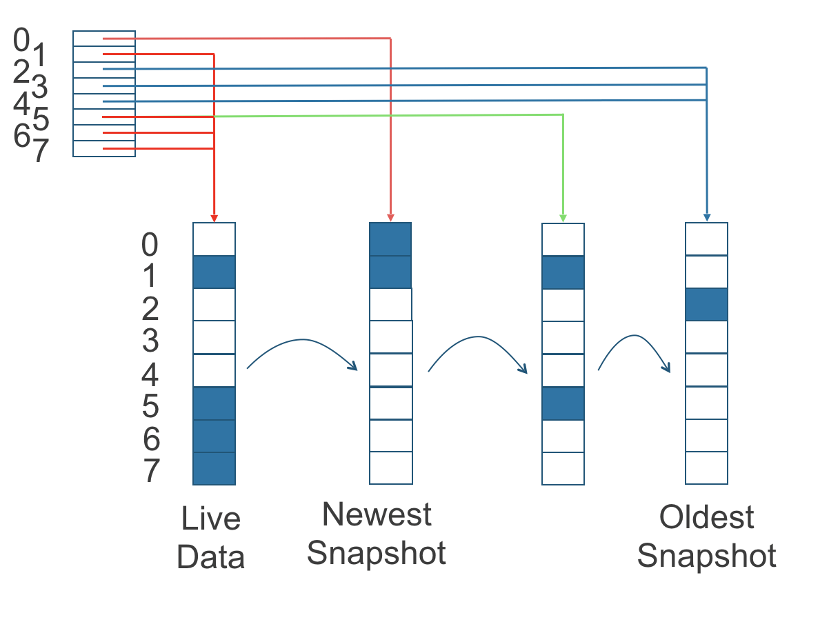
The figure above is color-coded to show which blocks contain the most recent data according to the read index, and the source of the latest data is also listed in the table below:
| Read Index | Source of the latest data |
|---|---|
| 0 | Newest snapshot |
| 1 | Live data |
| 2 | Oldest snapshot |
| 3 | Oldest snapshot |
| 4 | Oldest snapshot |
| 5 | Live data |
| 6 | Live data |
| 7 | Live data |
Note that as the green arrow shows in the figure above, Index 5 of the read index previously pointed to the second-oldest snapshot as the source of the most recent data, then it changed to point to the the live data when the 4K block of storage at Index 5 was overwritten by the live data.
The read index is kept in memory and consumes one byte for each 4K block. The byte-sized read index means you can take as many as 254 snapshots for each volume.
The read index consumes a certain amount of in-memory data structure for each replica. A 1 TB volume, for example, consumes 256 MB of in-memory read index.
2.3.2 How New Replicas are Added
When a new replica is added, the existing replicas are synced to the new replica. The first replica is created by taking a new snapshot from the live data.
The following steps show a more detailed breakdown of how Longhorn adds new replicas:
- The Longhorn Engine is paused.
- Let’s say that the chain of snapshots within the replica consists of the live data and a snapshot. When the new replica is created, the live data becomes the newest (second) snapshot and a new, blank version of live data is created.
- The new replica is created in WO (write-only) mode.
- The Longhorn Engine is unpaused.
- All the snapshots are synced.
- The new replica is set to RW (read-write) mode.
2.3.3. How Faulty Replicas are Rebuilt
Longhorn will always try to maintain at least given number of healthy replicas for each volume.
When the controller detects failures in one of its replicas, it marks the replica as being in an error state. The Longhorn Manager is responsible for initiating and coordinating the process of rebuilding the faulty replica.
To rebuild the faulty replica, the Longhorn Manager creates a blank replica and calls the Longhorn Engine to add the blank replica into the volume’s replica set.
To add the blank replica, the Engine performs the following operations:
- Pauses all read and write operations.
- Adds the blank replica in WO (write-only) mode.
- Takes a snapshot of all existing replicas, which will now have a blank differencing disk at its head.
- Unpauses all read and write operations. Only write operations will be dispatched to the newly added replica.
- Starts a background process to sync all but the most recent differencing disk from a good replica to the blank replica.
- After the sync completes, all replicas now have consistent data, and the volume manager sets the new replica to RW (read-write) mode.
Finally, the Longhorn Manager calls the Longhorn Engine to remove the faulty replica from its replica set.
2.4. Snapshots
The snapshot feature enables a volume to be reverted back to a certain point in history. Backups in secondary storage can also be built from a snapshot.
When a volume is restored from a snapshot, it reflects the state of the volume at the time the snapshot was created.
The snapshot feature is also a part of Longhorn’s rebuilding process. Every time Longhorn detects a replica is down, it will automatically take a (system) snapshot and start rebuilding it on another node.
2.4.1. How Snapshots Work
A snapshot is like a layer of an image, with the oldest snapshot used as the base layer, and newer snapshots on top. Data is only included in a new snapshot if it overwrites data in an older snapshot. Together, a chain of snapshots shows the current state of the data. For a more detailed breakdown of how data is read from a replica, refer to the section on read and write operations for replicas.
Snapshots cannot change after they are created, unless a snapshot is deleted, in which case its changes are conflated with the next most recent snapshot. New data is always written to the live version. New snapshots are always created from live data.
To create a new snapshot, the live data becomes the newest snapshot. Then a new, blank version of the live data is created, taking the place of the old live data.
2.4.2. Recurring Snapshots
To reduce the space taken by snapshots, user can schedule a recurring snapshot or backup with a number of snapshots to retain, which will automatically create a new snapshot/backup on schedule, then clean up for any excessive snapshots/backups.
2.4.3. Deleting Snapshots
Unwanted snapshots can be manually deleted through the UI. Any system generated snapshots will be automatically marked for deletion if the deletion of any snapshot was triggered.
In Longhorn, the latest snapshot cannot be deleted. This is because whenever a snapshot is deleted, Longhorn will conflate its content with the next snapshot, so that the next and later snapshot retains the correct content.
But Longhorn cannot do that for the latest snapshot since there is no more recent snapshot to be conflated with the deleted snapshot. The next “snapshot” of the latest snapshot is the live volume (volume-head), which is being read/written by the user at the moment, so the conflation process cannot happen.
Instead, the latest snapshot will be marked as removed, and it will be cleaned up next time when possible.
To clean up the latest snapshot, a new snapshot can be created, then the previous “latest” snapshot can be removed.
2.4.4. Storing Snapshots
Snapshots are stored locally, as a part of each replica of a volume. They are stored on the disk of the nodes within the Kubernetes cluster. Snapshots are stored in the same location as the volume data on the host’s physical disk.
2.4.5. Crash Consistency
Longhorn is a crash-consistent block storage solution.
It’s normal for the OS to keep content in the cache before writing into the block layer. This means that if all of the replicas are down, then Longhorn may not contain the changes that occurred immediately before the shutdown, because the content was kept in the OS-level cache and wasn’t yet transferred to the Longhorn system.
This problem is similar to problems that could happen if your desktop computer shuts down due to a power outage. After resuming the power, you may find some corrupted files in the hard drive.
To force the data to be written to the block layer at any given moment, the sync command can be manually run on the node, or the disk can be unmounted. The OS would write the content from the cache to the block layer in either situation.
Longhorn runs the sync command automatically before creating a snapshot.
3. Backups and Secondary Storage
A backup is an object in the backupstore, which is an NFS or S3 compatible object store external to the Kubernetes cluster. Backups provide a form of secondary storage so that even if your Kubernetes cluster becomes unavailable, your data can still be retrieved.
Because the volume replication is synchronized, and because of network latency, it is hard to do cross-region replication. The backupstore is also used as a medium to address this problem.
When the backup target is configured in the Longhorn settings, Longhorn can connect to the backupstore and show you a list of existing backups in the Longhorn UI.
If Longhorn runs in a second Kubernetes cluster, it can also sync disaster recovery volumes to the backups in secondary storage, so that your data can be recovered more quickly in the second Kubernetes cluster.
3.1. How Backups Work
A backup is created using one snapshot as a source, so that it reflects the state of the volume’s data at the time that the snapshot was created.
By contrast to a snapshot, a backup can be thought of as a flattened version of a chain of snapshots. Similar to the way that information is lost when a layered image is converted to a flat image, data is also lost when a chain of snapshots is converted to a backup. In both conversions, any overwritten data would be lost.
Because backups don’t contain snapshots, they don’t contain the history of changes to the volume data. After you restore a volume from a backup, the volume initially contains one snapshot. This snapshot is a conflated version of all the snapshots in the original chain, and it reflects the live data of the volume at the time at the time the backup was created.
While snapshots can be terabytes, backups are made of 2 MB files.
Each new backup of the same original volume is incremental, detecting and transmitting the changed blocks between snapshots. This is a relatively easy task because each snapshot is a differencing file and only stores the changes from the last snapshot.
To avoid storing a very large number of small blocks of storage, Longhorn performs backup operations using 2 MB blocks. That means that, if any 4K block in a 2MB boundary is changed, Longhorn will back up the entire 2MB block. This offers the right balance between manageability and efficiency.
Figure 3. The Relationship between Backups in Secondary Storage and Snapshots in Primary Storage
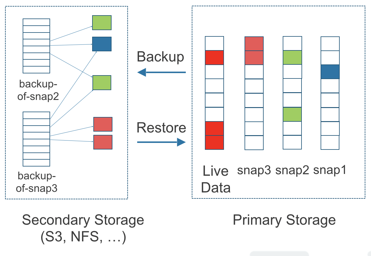
The above figure describes how backups are created from snapshots in Longhorn:
- The Primary Storage side of the diagram shows one replica of a Longhorn volume in the Kubernetes cluster. The replica consists of a chain of four snapshots. In order from newest to oldest, the snapshots are Live Data, snap3, snap2, and snap1.
- The Secondary Storage side of the diagram shows two backups in an external object storage service such as S3.
- In Secondary Storage, the color coding for backup-from-snap2 shows that it includes both the blue change from snap1 and the green changes from snap2. No changes from snap2 overwrote the data in snap1, therefore the changes from both snap1 and snap2 are both included in backup-from-snap2.
- The backup named backup-from-snap3 reflects the state of the volume’s data at the time that snap3 was created. The color coding and arrows indicate that backup-from-snap3 contains all of the dark red changes from snap3, but only one of the green changes from snap2. This is because one of the red changes in snap3 overwrote one of the green changes in snap2. This illustrates how backups don’t include the full history of change, because they conflate snapshots with the snapshots that came before them.
- Each backup maintains its own set of 2 MB blocks. Each 2 MB block is backed up only once. The two backups share one green block and one blue block.
When a backup is deleted from the secondary storage, Longhorn does not delete all the blocks that it uses. Instead, it performs a garbage collection periodically to clean up unused blocks from secondary storage.
The 2 MB blocks for all backups belonging to the same volume are stored under a common directory and can therefore be shared across multiple backups.
To save space, the 2 MB blocks that didn’t change between backups can be reused for multiple backups that share the same backup volume in secondary storage. Because checksums are used to address the 2 MB blocks, we achieve some degree of deduplication for the 2 MB blocks in the same volume.
Volume-level metadata is stored in volume.cfg. The metadata files for each backup (e.g., snap2.cfg) are relatively small because they only contain the offsets and checksums of all the 2 MB blocks in the backup.
Each 2 MB block (.blk file) is compressed.
3.2. Recurring Backups
Backup operations can be scheduled using the recurring snapshot and backup feature, but they can also be done as needed.
It’s recommended to schedule recurring backups for your volumes. If a backupstore is not available, it’s recommended to have the recurring snapshot scheduled instead.
Backup creation involves copying the data through the network, so it will take time.
3.3. Disaster Recovery Volumes
A disaster recovery (DR) volume is a special volume that stores data in a backup cluster in case the whole main cluster goes down. DR volumes are used to increase the resiliency of Longhorn volumes.
Because the main purpose of a DR volume is to restore data from backup, this type of volume doesn’t support the following actions before it is activated:
- Creating, deleting, and reverting snapshots
- Creating backups
- Creating persistent volumes
- Creating persistent volume claims
A DR volume can be created from a volume’s backup in the backup store. After the DR volume is created, Longhorn will monitor its original backup volume and incrementally restore from the latest backup. A backup volume is an object in the backupstore that contains multiple backups of the same volume.
If the original volume in the main cluster goes down, the DR volume can be immediately activated in the backup cluster, so it can greatly reduce the time needed to restore the data from the backup store to the volume in the backup cluster.
When a DR volume is activated, Longhorn will check the last backup of the original volume. If that backup has not already been restored, the restoration will be started, and the activate action will fail. Users need to wait for the restoration to complete before retrying.
The Backup Target in the Longhorn settings cannot be updated if any DR volumes exist.
After a DR volume is activated, it becomes a normal Longhorn volume and it cannot be deactivated.
3.4. Backupstore Update Intervals, RTO, and RPO
Typically incremental restoration is triggered by the periodic backup store update. Users can set backup store update interval in Setting - General - Backupstore Poll Interval.
Notice that this interval can potentially impact Recovery Time Objective (RTO). If it is too long, there may be a large amount of data for the disaster recovery volume to restore, which will take a long time.
As for Recovery Point Objective (RPO), it is determined by recurring backup scheduling of the backup volume. If recurring backup scheduling for normal volume A creates a backup every hour, then the RPO is one hour. You can check here to see how to set recurring backups in Longhorn.
The following analysis assumes that the volume creates a backup every hour, and that incrementally restoring data from one backup takes five minutes:
- If the Backupstore Poll Interval is 30 minutes, then there will be at most one backup worth of data since the last restoration. The time for restoring one backup is five minutes, so the RTO would be five minutes.
- If the Backupstore Poll Interval is 12 hours, then there will be at most 12 backups worth of data since last restoration. The time for restoring the backups is 5 * 12 = 60 minutes, so the RTO would be 60 minutes.
Appendix: How Persistent Storage Works in Kubernetes
To understand persistent storage in Kubernetes, it is important to understand Volumes, PersistentVolumes, PersistentVolumeClaims, and StorageClasses, and how they work together.
One important property of a Kubernetes Volume is that it has the same lifecycle as the Pod it belongs to. The Volume is lost if the Pod is gone. In contrast, a PersistentVolume continues to exist in the system until users delete it. Volumes can also be used to share data between containers inside the same Pod, but this isn’t the primary use case because users normally only have one container per Pod.
A PersistentVolume (PV) is a piece of persistent storage in the Kubernetes cluster, while a PersistentVolumeClaim (PVC) is a request for storage. StorageClasses allow new storage to be dynamically provisioned for workloads on demand.
How Kubernetes Workloads use New and Existing Persistent Storage
Broadly speaking, there are two main ways to use persistent storage in Kubernetes:
- Use an existing persistent volume
- Dynamically provision new persistent volumes
Existing Storage Provisioning
To use an existing PV, your application will need to use a PVC that is bound to a PV, and the PV should include the minimum resources that the PVC requires.
In other words, a typical workflow for setting up existing storage in Kubernetes is as follows:
- Set up persistent storage volumes, in the sense of physical or virtual storage that you have access to.
- Add a PV that refers to the persistent storage.
- Add a PVC that refers to the PV.
- Mount the PVC as a volume in your workload.
When a PVC requests a piece of storage, the Kubernetes API server will try to match that PVC with a pre-allocated PV as matching volumes become available. If a match can be found, the PVC will be bound to the PV, and the user will start to use that pre-allocated piece of storage.
if a matching volume does not exist, PersistentVolumeClaims will remain unbound indefinitely. For example, a cluster provisioned with many 50 Gi PVs would not match a PVC requesting 100 Gi. The PVC could be bound after a 100 Gi PV is added to the cluster.
In other words, you can create unlimited PVCs, but they will only be bound to PVs if the Kubernetes master can find a sufficient PV that has at least the amount of disk space required by the PVC.
Dynamic Storage Provisioning
For dynamic storage provisioning, your application will need to use a PVC that is bound to a StorageClass. The StorageClass contains the authorization to provision new persistent volumes.
The overall workflow for dynamically provisioning new storage in Kubernetes involves a StorageClass resource:
- Add a StorageClass and configure it to automatically provision new storage from the storage that you have access to.
- Add a PVC that refers to the StorageClass.
- Mount the PVC as a volume for your workload.
Kubernetes cluster administrators can use a Kubernetes StorageClass to describe the “classes” of storage they offer. StorageClasses can have different capacity limits, different IOPS, or any other parameters that the provisioner supports. The storage vendor specific provisioner is be used along with the StorageClass to allocate PV automatically, following the parameters set in the StorageClass object. Also, the provisioner now has the ability to enforce the resource quotas and permission requirements for users. In this design, admins are freed from the unnecessary work of predicting the need for PVs and allocating them.
When a StorageClass is used, a Kubernetes administrator is not responsible for allocating every piece of storage. The administrator just needs to give users permission to access a certain storage pool, and decide the quota for the user. Then the user can carve out the needed pieces of the storage from the storage pool.
StorageClasses can also be used without explicitly creating a StorageClass object in Kubernetes. Since the StorageClass is also a field used to match a PVC with a PV, a PV can be created manually with a custom Storage Class name, then a PVC can be created that asks for a PV with that StorageClass name. Kubernetes can then bind your PVC to the PV with the specified StorageClass name, even if the StorageClass object doesn’t exist as a Kubernetes resource.
Longhorn introduces a Longhorn StorageClass so that your Kubernetes workloads can carve out pieces of your persistent storage as necessary.
Horizontal Scaling for Kubernetes Workloads with Persistent Storage
The VolumeClaimTemplate is a StatefulSet spec property, and it provides a way for the block storage solution to scale horizontally for a Kubernetes workload.
This property can be used to create matching PVs and PVCs for Pods that were created by a StatefulSet.
Those PVCs are created using a StorageClass, so they can be set up automatically when the StatefulSet scales up.
When a StatefulSet scales down, the extra PVs/PVCs are kept in the cluster, and they are reused when the StatefulSet scales up again.
The VolumeClaimTemplate is important for block storage solutions like EBS and Longhorn. Because those solutions are inherently ReadWriteOnce, they cannot be shared between the Pods.
Deployments don’t work well with persistent storage if you have more than one Pod running with persistent data. For more than one pod, a StatefulSet should be used.
© 2019-2025 Longhorn Authors | Documentation Distributed under CC-BY-4.0
© 2025 The Linux Foundation. All rights reserved. The Linux Foundation has registered trademarks and uses trademarks. For a list of trademarks of The Linux Foundation, please see our Trademark Usage page.